After tinkering with Arduinos for more two and a half years, I still find it a lot of fun just to turn LEDs on and off. What's more fun than that? Turning on and off a bunch of LEDs. When I first got my starter kit I ordered an 8x8 LED matrix along with it. I have whatsoever no formal training in electronics, so it took me a while to figure out how to use that thing. Using the magic of Charlieplexing I was able to get a small, very tiny image lit. Not satisfied with having an extra 64 LEDs at my disposal, I wanted to go bigger; I needed a 3x3 of 8x8's, a 24x24, I wanted 576 LEDs to blink on and off at my whim. There were a few challenges along the way.
The Arduino UNO R3 doesn't have enough I/O pins for this by itself (I'd need a good 48). The simple solution to this was use use some 74HC595 shift registers. By daisy-chaining two sets of three (one to act as the row controller and the other for the column), I could get away with only using six pins. Though it's possible that I could have used less. The final product uses ten pins on the Arduino (to have better control of the MR and OE pins on the shift register).
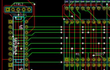
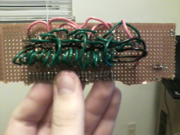
I originally planned to lay this all out on a protoboard, but as you can see from the below picture, it started to get really frustrating and confusing. I always wanted to learn how to make PCBs, so I though this would be a good opportunity to do so. I got myself a copy of KiCad, read a few tutorials, then went to work. I was actually surprised how easy it was to use this software. I did have some frustrations. Like that it's kind of half broken on Linux/GNU. It's only really usable under Windows or Wine (though there are still some quirks).

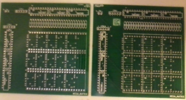
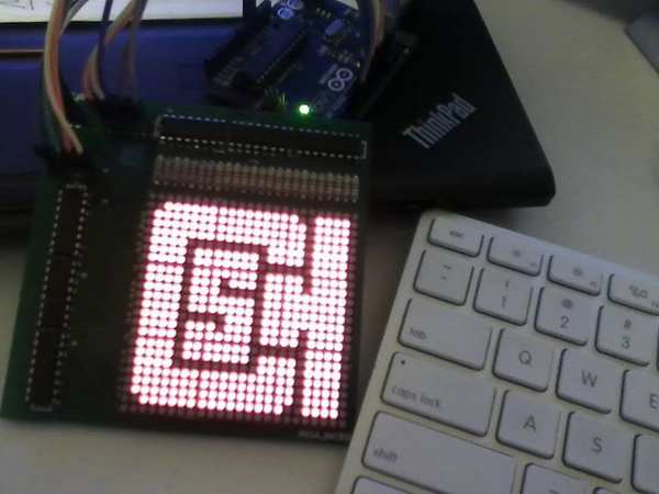
After receiving the print of the schematic, I found out that the footprints for the 788BS matrix were off, and the through holes where not wide enough. This wasn't a fun discovery. The next day, I spent a good two hours re-routing everything. I also added a CSH logo to the edge cuts. While I was waiting for the fixed boards to arrive I started to write the software to control the monstrous matrix. To my surprise, the circuit actually worked (this is on the bad board), and all I had to do was put globs of solder onto the pads and bend the pins on the 8x8 matrix. I also found out that it was a bit better to use a 200 Ohm resistor instead of 1K.

When using Arduino functions “digitalWrite(),” and “digitalRead(),” they may work okay for an 8x8 matrix, but I found out that on a 24x24, it doesn't work that well. I was getting around 75-ish frames per second. While I could have gotten away with showing a still image, it wasn't the easiest thing on the eyes. After doing some reading it seemed like writing some AVR C might be the remedy. One of the great things about the Arduino platform is that you can mix in AVR C code. After using C code to drive the matrix, I was getting around 625 frames per second. All of these measurements were made using timers and mathematics.

Now since I could display one image, the next logical step was to display a moving image. It only took another few hours of work to make this a possibility. The Arduino is always listening for data on its serial line. Once it has read in a full 72 bytes, it will display up a new picture. I also drafted a small pseudo scripting language where you can specify files to act as frames, assign them a delay, put them in a certain sequence, then have it loop.

If you want to check out the code for the project, you can find the repo right here: https://github.com/define-private-public/MEGA_MATRIX
And if you want a board, just send me a message. I've got a few to spare.
