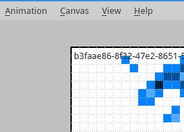
Back around mid to late July in 2014 I set out to create Blit. One year on now (as of last Wednesday), I've made a lot of progress from practically nothing. Thinking back I ask myself “why did I want to make Blit?”
I've made many other projects before. Some of them successes whereas others were really failures (cough buzz cough). Those projects had something in common. They were short, small, and contained. When I look back on all of the stuff that I've made, I noticed that there was nothing that I could call a “grand,” or “large,” project. I wanted something that I could call a major project that I built. More importantly I wanted to know how to manage a larger project; something I've never done before.
So I set a goal for myself: “Make something large. Something that you can never really call 'complete,' but work on it for an entire year.” That's what I did. I had nothing more than a silly GitHub streak to motivate me. It now says “371 days.” There were a few days where all I did was just update a TODO file, add some extra documentation, or ones that I didn't want to work on it at all (but I did anyways).
Blit still isn't really what I originally imaged it to be. Some sort of 2D Animation solution for pixel art and larger things (and hopefully pencil testing too). And I'm still not sure 100% what I want out of it. I consider what I've done so far to be nothing more than a prototype for a future vision.
I've met my goal of “work on something for a year,” but I plan to still chug along with it until I feel that I'm done. It's been fun so far.
Here are some stats:
- 371 days of continuous development (avg. one hour per day, more on the weekends)
- 75,868 additions / 47,902 deletions
- 7,846 lines of code (core application, mostly C++ w/ Qt)
- 2,887 commits
- 352 tickets
- 247 closed
- 105 open
- 43 more issues until the next one
- 12 (active) branches
- 1 (and a 1/2) milestones completed
- 1 contributor (me)
This is what my network looks like.
Cheers.
I was planning on doing another post after Imagine RIT, but I've been pretty busy. I was able to display off MEGA_MATRIX there along with a small fork of Blit where you can create animations then upload them to the device. It's was pretty popular with the kids. I'll be posting some of the creations soon enough.
Speaking of Blit I have been still working on it daily since the first release back in February. The big thing that I had to do was refactor the underlying monolithic Animation module into a more flexible and reusable system.
Some small stats:
- 3.5 months
- +1,100 lines of code (exactly)
- 655 commits
- 51 tickets (felt like 151)
I've also done a few other things like add a shape tool, line tool, fill tool (you know, the basics), and a few icons. There are many other features that I want to add too like exporting to GIF and video files. I think I'll be able to get them done for P-2.
It's been a while since my last update. In that time, I've been working on a few projects here in there. As for MEGA_MATRIX, I've added support for the Arduino MEGA and have been able to do a few proof of concept stuff for the Raspberry Pi. The Pi version right now can get a whopping 20K FPS in the native C version! The Pi version isn't too functional right now, but expect soon enough. Link to source on GitHub.
Since the end of the summer, I've been working on my own Animation tool. It's not much right now, but you can find Linux and OS X binaries right over here. Here's the first thing I was able to make with it, a bouncing ball:
![]()
After tinkering with Arduinos for more two and a half years, I still find it a lot of fun just to turn LEDs on and off. What's more fun than that? Turning on and off a bunch of LEDs. When I first got my starter kit I ordered an 8x8 LED matrix along with it. I have whatsoever no formal training in electronics, so it took me a while to figure out how to use that thing. Using the magic of Charlieplexing I was able to get a small, very tiny image lit. Not satisfied with having an extra 64 LEDs at my disposal, I wanted to go bigger; I needed a 3x3 of 8x8's, a 24x24, I wanted 576 LEDs to blink on and off at my whim. There were a few challenges along the way.
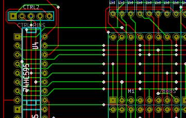
The Arduino UNO R3 doesn't have enough I/O pins for this by itself (I'd need a good 48). The simple solution to this was use use some 74HC595 shift registers. By daisy-chaining two sets of three (one to act as the row controller and the other for the column), I could get away with only using six pins. Though it's possible that I could have used less. The final product uses ten pins on the Arduino (to have better control of the MR and OE pins on the shift register).
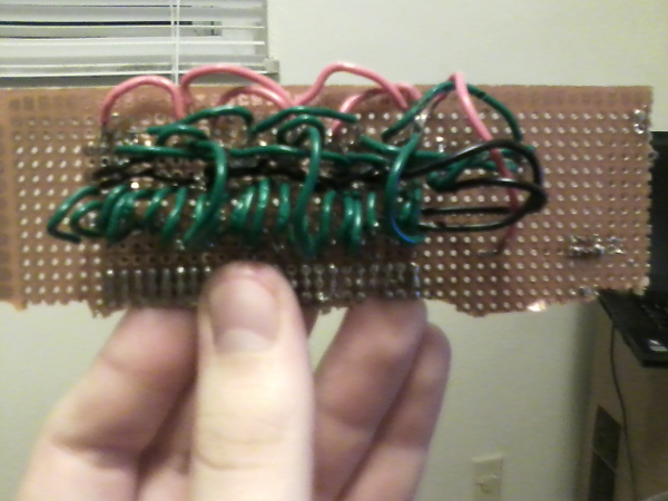
I originally planned to lay this all out on a protoboard, but as you can see from the below picture, it started to get really frustrating and confusing. I always wanted to learn how to make PCBs, so I though this would be a good opportunity to do so. I got myself a copy of KiCad, read a few tutorials, then went to work. I was actually surprised how easy it was to use this software. I did have some frustrations. Like that it's kind of half broken on Linux/GNU. It's only really usable under Windows or Wine (though there are still some quirks).
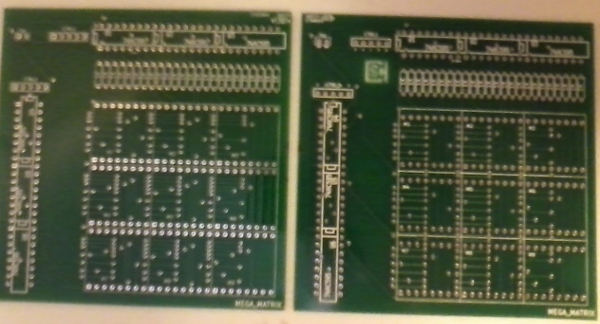
After receiving the print of the schematic, I found out that the footprints for the 788BS matrix were off, and the through holes where not wide enough. This wasn't a fun discovery. The next day, I spent a good two hours re-routing everything. I also added a CSH logo to the edge cuts. While I was waiting for the fixed boards to arrive I started to write the software to control the monstrous matrix. To my surprise, the circuit actually worked (this is on the bad board), and all I had to do was put globs of solder onto the pads and bend the pins on the 8x8 matrix. I also found out that it was a bit better to use a 200 Ohm resistor instead of 1K.
When using Arduino functions “digitalWrite(),” and “digitalRead(),” they may work okay for an 8x8 matrix, but I found out that on a 24x24, it doesn't work that well. I was getting around 75-ish frames per second. While I could have gotten away with showing a still image, it wasn't the easiest thing on the eyes. After doing some reading it seemed like writing some AVR C might be the remedy. One of the great things about the Arduino platform is that you can mix in AVR C code. After using C code to drive the matrix, I was getting around 625 frames per second. All of these measurements were made using timers and mathematics.

Now since I could display one image, the next logical step was to display a moving image. It only took another few hours of work to make this a possibility. The Arduino is always listening for data on its serial line. Once it has read in a full 72 bytes, it will display up a new picture. I also drafted a small pseudo scripting language where you can specify files to act as frames, assign them a delay, put them in a certain sequence, then have it loop.
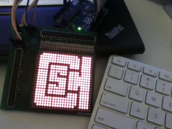
If you want to check out the code for the project, you can find the repo right here: https://github.com/define-private-public/MEGA_MATRIX
And if you want a board, just send me a message. I've got a few to spare.
I've been a little bit busy lately for the past week. I've had to move down to Cincinnati for my current Co-Op and it took much longer to prepare, move, and get settled in than I though it would. I've been a little bit delayed on making this post, but better late than never.
Early in my summer vacation I went down to D.C. on a small trip. While visiting the Smithsonian Institute and picked up one of those crystal growing kits. I remember playing with one when I was much younger (around ten or so) and thought it would be fun to grow another one. They didn't have the blue color anymore, so I opted to get a pack labeled “Emerald.” I thought it would be extra fun to do a timelapse of the crystal growing.
It took a few days to write a decent application to do this. My tools were C++, OpenCV, ffmpeg, and a very low resolution webcam. The app comes in two parts:
- Capture softare
- A script to compile images
Once everything was setup, I set the software to run for just five days, taking one picture per minute. The package said that it would only take that long for the crystal to grow, but that was a lie. I had to run the setup for two weeks and half a day. This resulted in 21,000+ images (totaling 1.5 GB of disk space).
I wanted to run the film at 30 fps, but 21,000+ images would result in something around fifteen minutes long, so I only used every fifth image for the final movie. You can it below:
I'm sorry that I don't have any other photographs of the crystal, or the “Magical Crystal Fun-Box,” that I grew it in. You'll just have to use your imagination for that last one. Source code for the application can be found here on my github.

